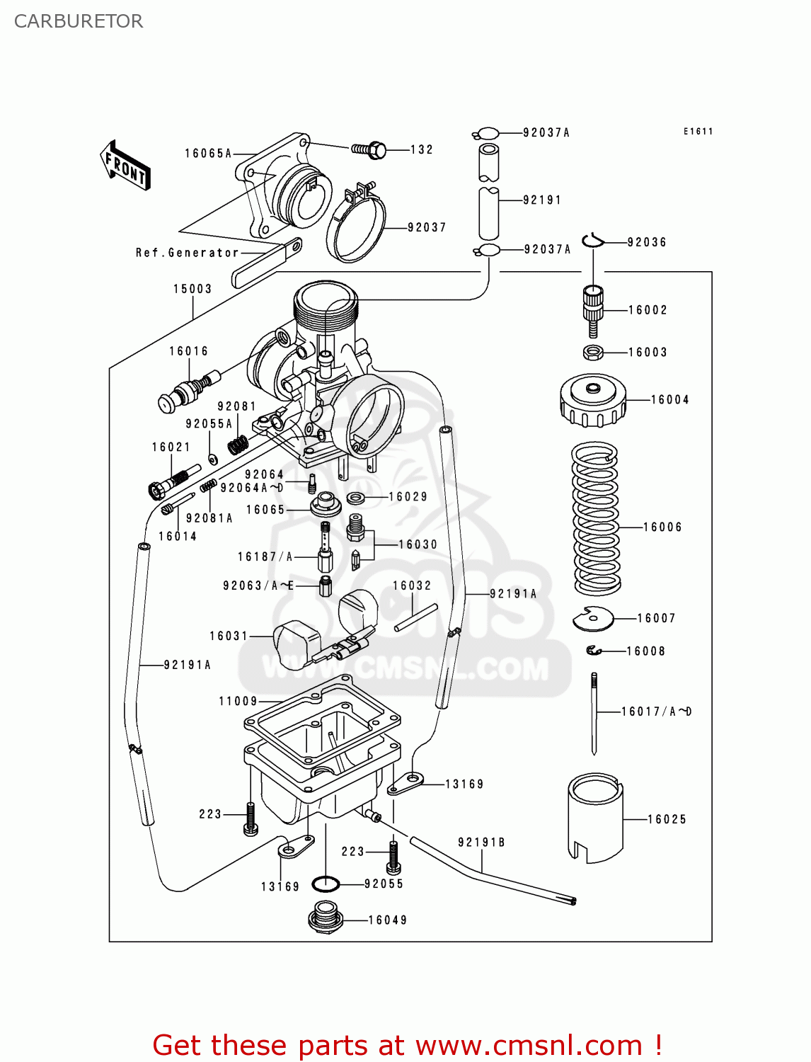
View and Download Kawasaki KX65 service manual online. KX65 Motorcycle pdf manual download. MODEL APPLICATION Year Model 2000 KX65-A1 2001.
Kx 65 Manual
. KX65 Motorcycle Service Manual.

Quick Reference Guide General Information Fuel System Cooling System Engine Top End Engine Right Side Engine Removal/Installation Engine Bottom End/Transmission 7 j Wheels/Tires Final Drive Brakes 10 j Suspension 11 j Steering 12 j Electrical System 13 j Appendix 14 j This quick reference guide will assist you in locating a desired topic or pro- cedure. All information contained in this publication is based on the latest product information available at the time of publication. Illustrations and photographs in this publication are intended for reference use only and may not depict actual model component parts. © 1999 Kawasaki Heavy Industries, Ltd.
12th Edition (1): Mar. LIST OF ABBREVIATIONS ampere(s) pound(s) ABDC after bottom dead center meter(s) alternating current minute(s) ATDC after top dead center newton(s) BBDC before bottom dead center pascal(s) bottom dead center horsepower BTDC before top dead center pound(s) per square inch °C degree(s) Celsius revolution direct current. Be alert for problems and non-scheduled which will help you distinguish different types maintenance. of information. Use proper tools and genuine Kawasaki mo- torcycle parts. Special tools, gauges, and NOTE ○ testers that are necessary when servicing This note symbol indicates points of par.
GENERAL INFORMATION 1-1 General Information Table of Contents Before Servicing.Model Identification. General Specifications.Periodic Maintenance Chart.Torque and Locking Agent. 1-11 Special Tools and Sealants.1-14 Cable, Wire and Hose Routing.1-18. 1-2 GENERAL INFORMATION Before Servicing Before starting to perform an inspection service or carry out a disassembly and reassembly opera- tion on a motorcycle, read the precautions given below. To facilitate actual operations, notes, illustra- tions, photographs, cautions, and detailed descriptions have been included in each chapter wherever necessary. GENERAL INFORMATION 1-3 Before Servicing (11) Press When using a press or driver to install a part such as a wheel bearing, apply a small amount of oil to the area where the two parts come in contact to ensure a smooth fit. (12)Ball Bearing and Needle Bearing Do not remove a ball bearing or a needle bearing unless it is absolutely necessary.

1-4 GENERAL INFORMATION Before Servicing (19)Inspection When parts have been disassembled, visually inspect these parts for the following conditions or other damage. If there is any doubt as to the condition of them, replace them with new ones. Abrasion Crack Hardening Warp Bent. GENERAL INFORMATION 1-5 Model Identification KX65-A1 Left Side View KX65-A1 Right Side View. KX65-A1 ∼ A2 Items ∼ ABF Dimensions Overall Length 1 580 mm 1 590 mm Overall Width 690 mm (KX65-A1), 730 mm (KX65-A2) 760 mm Overall Height 925 mm (KX65-A1), 935 mm (KX65-A2) 955 mm Wheelbase 1 110 mm 1 120 mm.
GENERAL INFORMATION 1-7 General Specifications KX65-A3 ∼ A6, A6F KX65-A1 ∼ A2 Items ∼ ABF Drive Train Primary Reduction System: Type Gear ← Reduction Ratio 3.500 (77/22) ← Clutch Type Wet, multi disc ← Transmission: Type 6-speed, constant mesh, return shift ←. 1-8 GENERAL INFORMATION General Specifications KX65-A3 ∼ A6, A6F KX65-A1 ∼ A2 Items ∼ ABF Brake Type: Front and Rear Single disc ← Effective Disc Diameter: Front 154.8 mm ← Rear 146 mm ← Specifications are subject to change without notice, and may not apply to every country.
GENERAL INFORMATION 1-9 Periodic Maintenance Chart The maintenance must be done in accordance with this chart to keep the motorcycle in good running condition. FREQUENCY After Every Every Every each 3 races 5 races 10 races race (or (or 7.5 (or 12.5 (or 25 required. 1-10 GENERAL INFORMATION Periodic Maintenance Chart FREQUENCY After Every Every Every each 3 races 5 races 10 races race (or (or 7.5 (or 12.5 (or 25 required OPERATION 2.5 hr.) hr.) hr.) hr.). Fuel hoses, connections - inspect †. GENERAL INFORMATION 1-11 Torque and Locking Agent Tighten all bolts and nuts to the proper torque using an accurate torque wrench. If insufficiently tightened, a bolt or nut may become damaged, strip an internal thread, or break and then fall out. The following table lists the tightening torque for the major bolts and nuts, and the parts requiring use of a non-permanent locking agent or liquid gasket.
2003 Rm 65 Owners Manual

1-12 GENERAL INFORMATION Torque and Locking Agent Torque Fastener Remarks Nm kgfm ftlb Engine Removal/Installation Engine Mounting Nuts Engine Mounting Nuts (KX65-A3 ∼) Swing Arm Pivot Shaft Nut Engine Bottom End/Transmission Cylinder Stud – – – L (Planted Side) Crankcase Bolts 0.90.